What is route filtering and why to use it?
In the context of network routing, route filtering is the process by which certain routes are not considered for inclusion in the local route database, or not advertised to one’s neighbours. Route filtering is particularly important for use on large networks or on the Internet where it is used for a variety of reasons. To facilitate route filtering a distribute-list is used to control routing updates either coming to or from a router.
In the example below we will configure only 3 routers that will all participate in dynamic routing. However, behind each router eight unique networks will exist. These networks will only be used for the demonstration but are designed in such a way that makes summarization very easy. For example we are using 172.16.0.0-172.16.7.0 that can easily be summarized as 172.16.0.0 255.255.248.0 or /21 or further subnetted into smaller address spaces such as 172.16.0.0 255.255.252.0 or /22.

Steps to configure route filtering
R1(config)#interface FastEthernet0/0.1
R1(config-subif)#encapsulation dot1Q 1
R1(config-subif)#ip address 172.16.0.1 255.255.255.0
!
R1(config)#interface FastEthernet0/0.2
R1(config-subif)#encapsulation dot1Q 2
R1(config-subif)#ip address 172.16.1.1 255.255.255.0
!
R1(config)#interface FastEthernet0/0.3
R1(config-subif)#encapsulation dot1Q 3
R1(config-subif)#ip address 172.16.2.1 255.255.255.0
!
R1(config)#interface FastEthernet0/0.4
R1(config-subif)#encapsulation dot1Q 4
R1(config-subif)#ip address 172.16.3.1 255.255.255.0
!
R1(config)#interface FastEthernet0/0.5
R1(config-subif)#encapsulation dot1Q 5
R1(config-subif)#ip address 172.16.4.1 255.255.255.0
!
R1(config)#interface FastEthernet0/0.6
R1(config-subif)#encapsulation dot1Q 6
R1(config-subif)#ip address 172.16.5.1 255.255.255.0
!
R1(config)#interface FastEthernet0/0.7
R1(config-subif)#encapsulation dot1Q 7
R1(config-subif)#ip address 172.16.6.1 255.255.255.0
!
R1(config)#interface FastEthernet0/0.8
R1(config-subif)#encapsulation dot1Q 8 native
R1(config-subif)#ip address 172.16.7.1 255.255.255.0
!
R1(config)#interface FastEthernet1/0
R1(config-if)#ip address 10.1.1.1 255.255.255.252
!
R1(config)#interface FastEthernet1/1
R1(config-if)#ip address 10.1.1.5 255.255.255.252
Step 2: Configure a OSPF routing process and advertise all applicable networks.
R1(config)#router ospf 101
R1(config-router)#network 10.1.1.0 0.0.0.3 area 0
R1(config-router)#network 10.1.1.4 0.0.0.3 area 0
R1(config-router)#network 10.1.2.0 0.0.0.3 area 2
R1(config-router)#network 172.16.0.0 0.0.0.255 area 0
R1(config-router)#network 172.16.1.0 0.0.0.255 area 0
R1(config-router)#network 172.16.2.0 0.0.0.255 area 0
R1(config-router)#network 172.16.3.0 0.0.0.255 area 0
R1(config-router)#network 172.16.4.0 0.0.0.255 area 0
R1(config-router)#network 172.16.5.0 0.0.0.255 area 0
R1(config-router)#network 172.16.6.0 0.0.0.255 area 0
R1(config-router)#network 172.16.7.0 0.0.0.255 area 0
Step 3: Repeat steps 1 and 2 on R2 and R3 where R2 will make use of networks 172.16.8.0-172.16.15.0 and R3 will make use of 172.16.16.0-172.16.23.0.
Step 4: On R1 router define the network boundary for 172.16.0.0, 172.16.8.0 and 172.16.16.0 as 255.255.252.0 or /30 by not advertising the next four sequential subnets. This will advertise only the first four networks out of the 255.255.248.0 or /29 address space.
R1(config)#router ospf 101
R1(config-router)#area 0 range 172.16.4.0 255.255.252.0 not-advertise
R1(config-router)#area 0 range 172.16.12.0 255.255.252.0 not-advertise
R1(config-router)#area 0 range 172.16.20.0 255.255.252.0 not-advertise
Verify the configuration
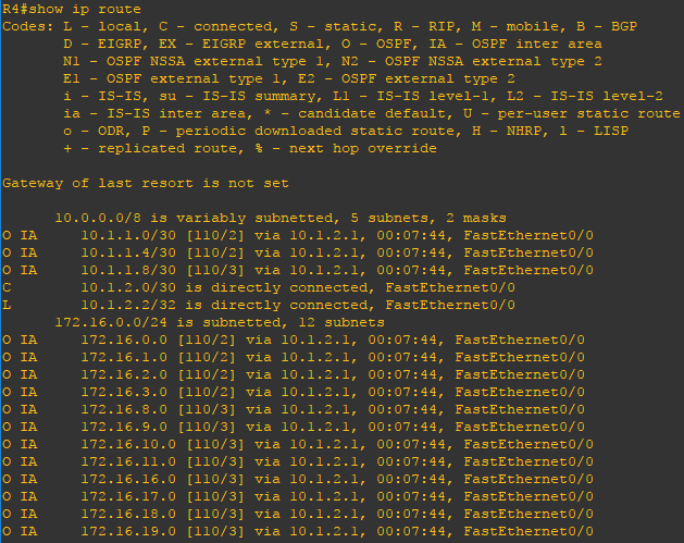
Now that the configuration is finished lets verify our neighbors and routes. Using the show ip ospf neighbors and show ip route commands you can verify the remote routes to which your router has formed and adjacency and verify the expected routes are being advertised. Use the ping command to verify connectivity. Per the below routing table on R4 we can view the first four network address spaces behind R1, R2 and R3 have been advertised.

