What is load sharing and why to use it?
Load balancing with BGP is not possible in a multihomed environment with two ISPs. BGP selects only the single best path to a destination among the BGP paths that are learned from different ASs, which makes load balancing impossible. However, load sharing is possible in such multihomed BGP networks. To use load sharing one or more route-maps must be configured to route traffic over one or more links. In the event of a path used by the route-map is unavailable the normal BGP route failover process will occur providing link redundancy.
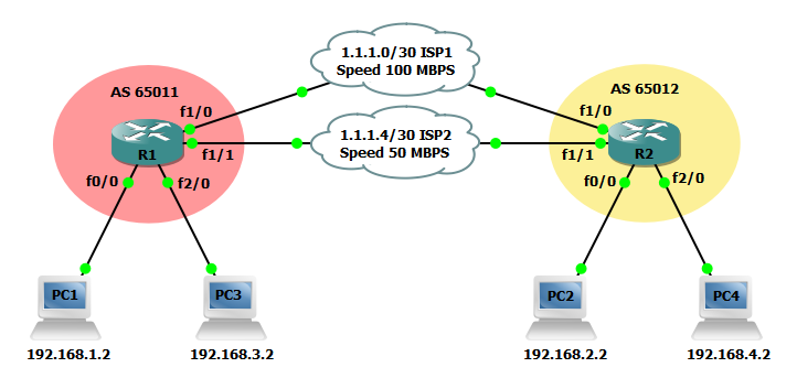
In the below example we will configure two BGP routers and four end-user devices. Each router will have two redundant WAN connections to the other router. We will also configure access-list and route-maps to facilitate load sharing across both links despite only one route being installed. In the event of a link becoming unavailable failover and failback must occur automatically without any any manual intervention.

Steps to configure BGP load sharing
R1(config)#interface FastEthernet0/0
R1(config-if)#ip address 192.168.1.1 255.255.255.0
!
R1(config)#interface FastEthernet1/0
R1(config-if)#ip address 1.1.1.1 255.255.255.252
!
R1(config)#interface FastEthernet1/1
R1(config-if)#bandwidth 50000
R1(config-if)#ip address 1.1.1.5 255.255.255.252
!
R1(config)#interface FastEthernet2/0
R1(config-if)#ip address 192.168.3.1 255.255.255.0
R2(config)#interface FastEthernet0/0
R2(config-if)#ip address 192.168.2.1 255.255.255.0
!
R2(config)#interface FastEthernet1/0
R2(config-if)#ip address 1.1.1.2 255.255.255.252
!
R2(config)#interface FastEthernet1/1
R2(config-if)#bandwidth 50000
R2(config-if)#ip address 1.1.1.6 255.255.255.252
!
R2(config)#interface FastEthernet2/0
R2(config-if)#ip address 192.168.4.1 255.255.255.0
Step 2: Enable a BGP routing process with a unique AS number and enable BGP routing on all applicable IP networks.
R1(config)#router bgp 65011
R1(config-router)#bgp router-id 192.168.1.1
R1(config-router)#bgp log-neighbor-changes
R1(config-router)#network 1.1.1.0 mask 255.255.255.252
R1(config-router)#network 1.1.1.4 mask 255.255.255.252
R1(config-router)#network 192.168.1.0
R1(config-router)#network 192.168.3.0
R1(config-router)#neighbor 1.1.1.2 remote-as 65012
R1(config-router)#neighbor 1.1.1.6 remote-as 65012
R2(config)#router bgp 65012
R2(config-router)#bgp router-id 192.168.2.1
R2(config-router)#bgp log-neighbor-changes
R2(config-router)#network 1.1.1.0 mask 255.255.255.252
R2(config-router)#network 1.1.1.4 mask 255.255.255.252
R2(config-router)#network 192.168.2.0
R2(config-router)#network 192.168.4.0
R2(config-router)#neighbor 1.1.1.1 remote-as 65011
R2(config-router)#neighbor 1.1.1.5 remote-as 65011
Step 3: Configure two access-list and two route-maps on R1. This will facilitate routing traffic for 192.168.3.0 and 192.168.4.0 over ISP2.
R1(config)#access-list 10 permit 192.168.3.0 0.0.0.255
R1(config)#access-list 10 permit 192.168.4.0 0.0.0.255
!
R1(config)#route-map PBR-PERMIT-ISP2 permit 10
R1(config-route-map)#match ip address 10
R1(config-route-map)#set local-preference 200
!
R1(config)#route-map PBR-PERMIT-ISP2 permit 20
!
R1(config)#router bgp 65011
R1(config-router)#neighbor 1.1.1.6 route-map PBR-PERMIT-ISP2 in
Step 4: Repeat step 3 on R2 so traffic for 192.168.3.0 and 192.168.4.0 will be routed over ISP2.
R2(config)#access-list 10 permit 192.168.3.0 0.0.0.255
R2(config)#access-list 10 permit 192.168.4.0 0.0.0.255
!
R2(config)#route-map PBR-PERMIT-ISP2 permit 10
R2(config-route-map)#match ip address 10
R2(config-route-map)#set local-preference 200
!
R2(config)#route-map PBR-PERMIT-ISP2 permit 20
!
R2(config)#router bgp 65012
R2(config-router)#neighbor 1.1.1.5 route-map PBR-PERMIT-ISP2 in
Verify the configuration
Now that the configuration is finished lets verify our neighbors and routes. Using the show ip bgp neighbors and show ip route commands you can verify the remote routes to which your router has formed and adjacency and verify the expected routes are being advertised. Use the ping and traceroute commands to verify connectivity and the paths traffic takes to reach each destination. Using PC1 we can verify PC1 uses ISP1 to reach PC2 and PC1 uses ISP2 to reach PC4.

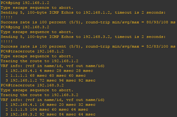
Performing the same task in reverse from PC4 we can verify PC4 uses ISP1 to reach PC1 and PC4 uses ISP2 to reach PC3. This confirms manual load sharing is working as intended.

Lastly, let’s test failover. On R1 and R2 shut interface FastEthernet1/1. After 180 seconds BGP will converge and all traffic for all sources will be routed over ISP1. Repeat the ping and traceroute commands to verify connectivity. Bring interface FastEthernet1/1 back up on R1 and R2 and shut interface FastEthernet1/0. Once again, after 180 seconds BGP will converge and all traffic for all sources will be routed over ISP2. Bring FastEthernet1/0 back up on R1 and R2 and traffic should be routed as expect per the route-map configuration.

