What is VLAN trunking protocol and why to use it?
VLAN Trunking Protocol (VTP) is a Cisco proprietary protocol that propagates the definition of Virtual Local Area Networks (VLAN) between switching systems. VTP carries VLAN information to all the switches in a VTP domain and advertisements are sent over 802.1Q trunks. Using VTP, each switch advertises the management domain, configuration revision number, known VLANs and their specific parameters. The four VTP modes configurable are server, client, transparent, and off.
In VTP server mode, you can create, modify, and delete VLANs and specify other configuration parameters, such as VTP version and VTP pruning, for the entire VTP domain. VTP servers advertise their VLAN configuration to other switches in the same VTP domain and synchronize their VLAN configuration with other switches based on advertisements received over trunk links. VTP server is the default mode. VTP clients behave the same way as VTP servers, but you cannot create, change, or delete VLANs on a VTP client. VTP transparent switches do not participate in VTP but do forward VTP advertisements that they receive out their trunk ports in VTP Version 2.
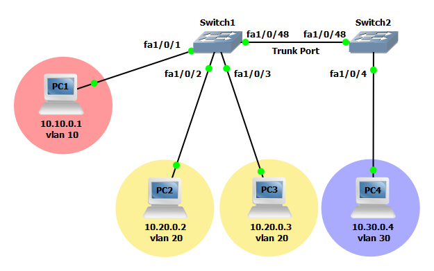
In the example below we will configure two switches in a VTP domain. Switch1 will be staged with three vlans, 10, 20, and 30. Each port configured on the switch will be configured as access ports unconditionally allowing only a single device to be connected with the exception of a single trunk port to pass vlan information between both switches. All devices within a vlan should be able to access other devices in the same vlan. Devices connected to ports in other vlans should only be able to access other devices external to the same vlan if configured with a switch virtual interface (SVI).

Step to configure VLAN trunking protocol
Switch1(config)#int vlan 1
Switch1(config-if)#ip add 10.1.0.1 255.255.255.0
Switch1(config-if)#no shut
!
Switch2(config)#int vlan 1
Switch2(config-if)#ip add 10.1.0.2 255.255.255.0
Switch2(config-if)#no shut
Step 2: Configure Switch1 as a VTP server and configure the VTP version, VTP domain, VTP password and enable VTP pruning.
Switch1(config)#vtp mode server
Switch1(config)#vtp version 3
Switch1(config)#vtp domain vtp.domain.local
Switch1(config)#vtp password vtppasswordhere
Switch1(config)#vtp pruning
Switch1#vtp primary
NOTE: The command vtp primary requires you to exit config mode to enter the command in global mode.
Step 3: Configure Switch2 as a VTP client and configure the VTP version, VTP domain, VTP password and enable VTP pruning.
Switch2(config)#vtp mode client
Switch2(config)#vtp version 3
Switch2(config)#vtp domain vtp.domain.local
Switch2(config)#vtp password vtppasswordhere
Switch2(config)#vtp pruning
Step 4: Configure interface FastEthernet1/0/48 on both switches as a trunk port to establish VTP connectivity.
Switch1(config)#interface FastEthernet1/0/48
Switch1(config-if)#switchport mode trunk
!
Switch2(config)#interface FastEthernet1/0/48
Switch2(config-if)#switchport mode trunk
Step 5: Configure interface GigabitEthernet0/4 on Switch2 for vlan 30 and move PC4 to Switch2.
Switch2(config)#interface GigabitEthernet0/4
Switch2(config-if)#switchport mode access
Switch2(config-if)#switchport access vlan 30
Switch2(config-if)#no shut
Verify the configuration
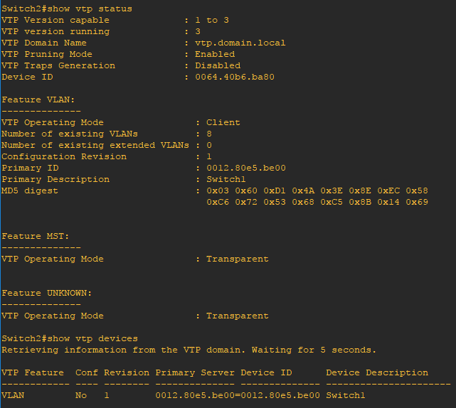
Now that the configuration is finished lets verify the vlan assignments. Using the show vlan, show ip route, show vtp status, show vtp devices and show ip int brief commands you can verify each vlan in the local vlan database, the local routing table, the IP configuration of each vlan SVI, and VTP information. By viewing the local vlan database you can also verify which vlans have been propagated between switches and which ports have been assigned to each vlan. Use the ping command to verify connectivity within a vlan. You should be able to ping computers in other vlans configured with SVIs from Switch2.

