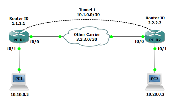
Step 1: Configure PE-R1 and PE-R2 interfaces and OSPF to establish basic connectivity. We will also create a loopback interface to serve as as the router-id for the OSPF process and LDP and configure the applicable interfaces for dynamic MPLS forwarding.
PE-R1(config)#interface Loopback0
PE-R1(config-if)#ip address 1.1.1.1 255.255.255.255
!
PE-R1(config)#interface FastEthernet0/0
PE-R1(config-if)#ip address 3.3.3.1 255.255.255.252
!
PE-R1(config)#router ospf 101
PE-R1(config-router)#router-id 1.1.1.1
PE-R1(config-router)#network 1.1.1.1 0.0.0.0 area 0
PE-R1(config-router)#network 10.1.0.0 0.0.0.3 area 0
PE-R2(config)#interface Loopback0
PE-R2(config-if)#ip address 2.2.2.2 255.255.255.255
!
PE-R2(config)#interface FastEthernet0/0
PE-R2(config-if)#ip address 3.3.3.2 255.255.255.252
!
PE-R2(config)#router ospf 101
PE-R2(config-router)#router-id 2.2.2.2
PE-R2(config-router)#network 2.2.2.2 0.0.0.0 area 0
PE-R2(config-router)#network 10.1.0.0 0.0.0.3 area 0
Step 2: Forcibly change the LDP router id on PE-R1 and PE-R2.
PE-R1(config)#mpls ldp router-id Loopback0 force
PE-R2(config)#mpls ldp router-id Loopback0 force
Step 3: Configure vrf vpn1 for Customer 1 on PE-R1 and PE-R2. We will also enable the VRF on the applicable interfaces and configure an IP address on the interfaces as well.
PE-R1(config)#ip vrf vpn1
PE-R1(config-vrf)#rd 65000:101
PE-R1(config-vrf)#route-target export 65000:101
PE-R1(config-vrf)#route-target import 65000:101
!
PE-R1(config)#interface FastEthernet0/1
PE-R1(config-if)#ip vrf forwarding vpn1
PE-R1(config-if)#ip address 10.10.0.1 255.255.255.0
PE-R2(config)#ip vrf vpn1
PE-R2(config-vrf)#rd 65000:101
PE-R2(config-vrf)#route-target export 65000:101
PE-R2(config-vrf)#route-target import 65000:101
!
PE-R2(config)#interface FastEthernet0/1
PE-R2(config-if)#ip vrf forwarding vpn1
PE-R2(config-if)#ip address 10.20.0.1 255.255.255.0
Step 4: Configure a tunnel interface on both PE-R1 and PE-R2.
PE-R1(config)#interface Tunnel1
PE-R1(config-if)#ip address 10.1.0.1 255.255.255.252
PE-R1(config-if)#mpls ip
PE-R1(config-if)#tunnel source 3.3.3.1
PE-R1(config-if)#tunnel destination 3.3.3.2
PE-R2(config)#interface Tunnel1
PE-R2(config-if)#ip address 10.1.0.2 255.255.255.252
PE-R2(config-if)#mpls ip
PE-R2(config-if)#tunnel source 3.3.3.2
PE-R2(config-if)#tunnel destination 3.3.3.1
Step 5: Next configure a BGP process on PE-R1 and PE-R2 to facilitate advertisements of customer networks over the MPLS network.
PE-R1(config-router)#router bgp 65000
PE-R1(config-router)#bgp log-neighbor-changes
PE-R1(config-router)#neighbor 2.2.2.2 remote-as 65000
PE-R1(config-router)#neighbor 2.2.2.2 update-source Loopback0
!
PE-R1(config-router)#address-family vpnv4
PE-R1(config-router-af)#neighbor 2.2.2.2 activate
PE-R1(config-router-af)#neighbor 2.2.2.2 send-community extended
PE-R1(config-router-af)#exit-address-family
!
PE-R1(config-router)#address-family ipv4 vrf vpn1
PE-R1(config-router-af)#redistribute connected
PE-R1(config-router-af)#neighbor 10.1.0.2 remote-as 65000
PE-R1(config-router-af)#neighbor 10.1.0.2 activate
PE-R1(config-router-af)#exit-address-family
PE-R2(config-router)#router bgp 65000
PE-R2(config-router)#bgp log-neighbor-changes
PE-R2(config-router)#neighbor 1.1.1.1 remote-as 65000
PE-R2(config-router)#neighbor 1.1.1.1 update-source Loopback0
!
PE-R2(config-router)#address-family vpnv4
PE-R2(config-router-af)#neighbor 1.1.1.1 activate
PE-R2(config-router-af)#neighbor 1.1.1.1 send-community extended
PE-R2(config-router-af)#exit-address-family
!
PE-R2(config-router)#address-family ipv4 vrf vpn1
PE-R2(config-router-af)#redistribute connected
PE-R2(config-router-af)#neighbor 10.1.0.1 remote-as 65000
PE-R2(config-router-af)#neighbor 10.1.0.1 activate
PE-R2(config-router-af)#exit-address-family