What is a Layer 2 MPLS VPN and why to use it?

Layer 2 VPNs are a type of Virtual Private Network (VPN) that uses MPLS labels to transport data. The communication occurs between routers that are known as Provider Edge routers (PEs), as they sit on the edge of the provider's network, next to the customer's network. Internet providers who have an existing Layer 2 network may choose to use these VPNs instead of the other common MPLS VPN, Layer 3. Layer 2 VPNs uses the Label Distribution Protocol (LDP) to communicate between PE routers and established a virtual circuit providing the customer one or more private point-to-point connection.

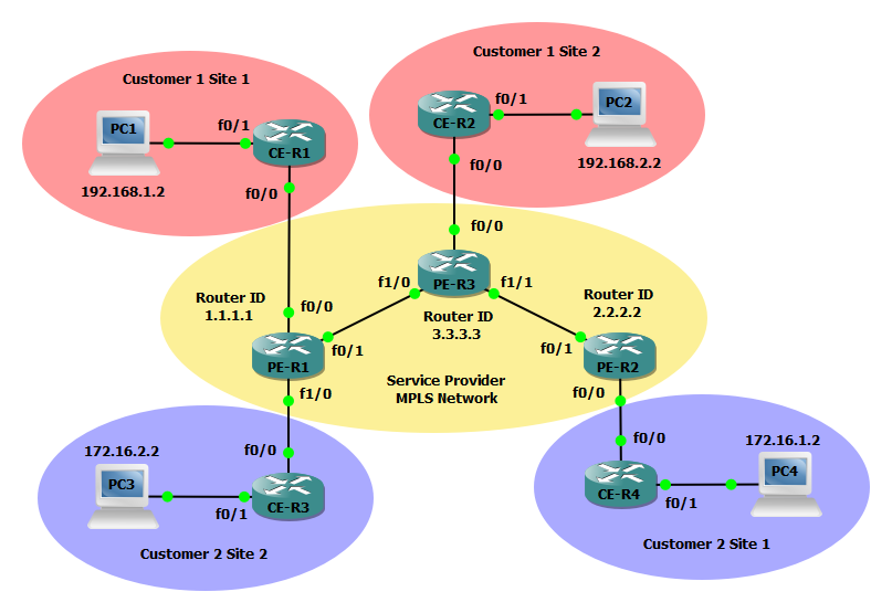
In the example below we will configure three MPLS service provider routers (PEs), two routers for customer 1 (CE), and two additional routers for Customer 2 (CE). The service provider MPLS network will run a basic OSPF configuration and all customer routers will simply use static routers to point to their other sites. Both customer 1 and customer 2 must be provisioned a private virtual circuit to facilitate a direct point-to-point connection. Using CDP both customer routers should appear directly connected.

Steps to configure a Layer 2 MPLS VPN

Step 1: Configure PE-R1, PE-R2, and PE-R3 interfaces and OSPF to establish basic connectivity. We will also create a loopback interface to serve as as the router-id for the OSPF process and LDP.

PE-R1(config)#interface Loopback0
PE-R1(config-if)#ip address 1.1.1.1 255.255.255.255
!
PE-R1(config)#interface FastEthernet0/1
PE-R1(config-if)#ip address 13.13.13.1 255.255.255.252
!
PE-R1(config)#router ospf 101
PE-R1(config-router)#router-id 1.1.1.1
PE-R1(config-router)#network 1.1.1.1 0.0.0.0 area 0
PE-R1(config-router)#network 13.13.13.0 0.0.0.3 area 0
PE-R2(config)#interface Loopback0
PE-R2(config-if)#ip address 2.2.2.2 255.255.255.255
!
PE-R2(config)#interface FastEthernet0/1
PE-R2(config-if)#ip address 23.23.23.1 255.255.255.252
!
PE-R2(config)#router ospf 101
PE-R2(config-router)#router-id 2.2.2.2
PE-R2(config-router)#network 2.2.2.2 0.0.0.0 area 0
PE-R2(config-router)#network 23.23.23.0 0.0.0.3 area 0
PE-R3(config)#interface Loopback0
PE-R3(config-if)#ip address 3.3.3.3 255.255.255.255
!
PE-R3(config)#interface FastEthernet1/0
PE-R3(config-if)#ip address 13.13.13.2 255.255.255.252
!
PE-R3(config)#interface FastEthernet1/1
PE-R3(config-if)#ip address 23.23.23.2 255.255.255.252
!
PE-R3(config)#router ospf 101
PE-R3(config-router)#router-id 3.3.3.3
PE-R3(config-router)#network 3.3.3.3 0.0.0.0 area 0
PE-R3(config-router)#network 13.13.13.0 0.0.0.3 area 0

Step 2: Forcibly change the LDP router id on PE-R1, PE-R2, and PE-R3.

PE-R1(config)#mpls ldp router-id Loopback0 force
PE-R2(config)#mpls ldp router-id Loopback0 force
PE-R3(config)#mpls ldp router-id Loopback0 force

Step 3: Configure a pseudowire-class and configure dynamic MPLS between PE devices on PE-R1, PE-R2, and PE-R3.

PE-R1(config-if)#interface FastEthernet0/1
PE-R1(config-if)#mpls ip
!
PE-R1(config)#pseudowire-class ETHERNET
PE-R1(config-pw-class)#encapsulation mpls
PE-R2(config)#pseudowire-class ETHERNET
PE-R2(config-pw-class)#encapsulation mpls
!
PE-R2(config-if)#interface FastEthernet0/1
PE-R2(config-if)#mpls ip
PE-R3(config)#pseudowire-class ETHERNET
PE-R3(config-pw-class)#encapsulation mpls
!
PE-R3(config)#interface FastEthernet1/0
PE-R3(config-if)#mpls ip
!
PE-R3(config)#interface FastEthernet1/1
PE-R3(config-if)#mpls ip

Step 4: Configure virtual circuits 101 and 102 to provide a private point-to-point for Customer 1 and Customer 2. The virtual circuit 101 is for Customer 1 and 102 is for Customer 2. The xconnect command followed by the IP address of the peer router will establish the connection for the local interface into the private virtual circuit.

PE-R1(config)#interface FastEthernet0/0
PE-R1(config-if)#duplex full
PE-R1(config-if)#xconnect 3.3.3.3 101 pw-class ETHERNET
!
PE-R1(config)#interface FastEthernet1/0
PE-R1(config-if)#duplex full
PE-R1(config-if)#xconnect 2.2.2.2 102 pw-class ETHERNET
PE-R2(config)#interface FastEthernet0/0
PE-R2(config-if)#duplex full
PE-R2(config-if)#xconnect 1.1.1.1 102 pw-class ETHERNET
PE-R3(config)#interface FastEthernet0/0
PE-R3(config-if)#duplex full
PE-R3(config-if)#xconnect 1.1.1.1 101 pw-class ETHERNET

Steps to configure Customer 1 CE devices

Step 5: Configure Customer 1 CE-R1 and CE-R2 with a basic configuration. Each router will have a single static route directing all unknown traffic to the adjacent site router.

CE-R1(config)#interface FastEthernet0/0
CE-R1(config-if)#ip address 10.1.0.1 255.255.255.252
!
CE-R1(config)#interface FastEthernet0/1
CE-R1(config-if)#ip address 192.168.1.1 255.255.255.0
!
CE-R1(config)#ip route 0.0.0.0 0.0.0.0 10.1.0.2
CE-R2(config)#interface FastEthernet0/0
CE-R2(config-if)#ip address 10.1.0.2 255.255.255.252
!
CE-R2(config)#interface FastEthernet0/1
CE-R2(config-if)#ip address 192.168.2.1 255.255.255.0
!
CE-R2(config)#ip route 0.0.0.0 0.0.0.0 10.1.0.1

Steps to configure Customer 2 CE devices

Step 6: Configure Customer 2 CE-R3 and CE-R4 with a basic configuration. Each router will again have a single static route directing all unknown traffic to the adjacent site router.

CE-R3(config-if)#ip address 10.2.0.2 255.255.255.252
!
CE-R3(config)#interface FastEthernet0/1
CE-R3(config-if)#ip address 172.16.2.1 255.255.255.0
!
CE-R3(config)#ip route 0.0.0.0 0.0.0.0 10.2.0.1
CE-R4(config)#interface FastEthernet0/0
CE-R4(config-if)#ip address 10.2.0.1 255.255.255.252
!
CE-R4(config)#interface FastEthernet0/1
CE-R4(config-if)#ip address 172.16.1.1 255.255.255.0
!
CE-R4(config)#ip route 0.0.0.0 0.0.0.0 10.2.0.2

Verify the configuration

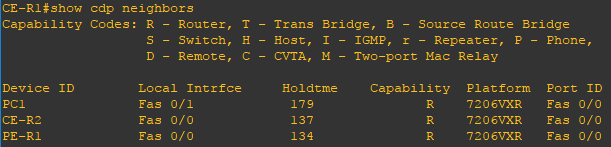
Now that the configuration is finished lets verify our neighbors and routes. Using the show cdp neighborsshow mpls forwarding-table, and show mpls l2transport vc # commands you can verify the MPLS deployment. Use the ping command to verify connectivity from PC1 to PC2 from PC3 to PC4. In Customer 1 Site 1 issue the show cdp neighbors command to verify CE-R2 appears directly connected.

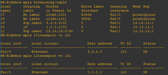
Use the show mpls forwarding-table to verify the virtual circuits on PE-R1, PE-R2, and PE-R3. Using the show mpls l2transport vc 101 and show mpls l2transport vc 102 commands you can verify the local interface participating in the virtual circuit and the destination where the virtual circuit is terminated. You can repeat on the other provider routers to verify the virtual configuration end to end.

Related Posts

Cisco Networking

BGP Load Sharing

Load balancing with BGP is not possible in a multihomed environment with two ISPs. BGP selects only the single best path to a destination among the BGP paths that are learned from different ASs, which Read more…

Cisco Firewall

Configuring Dynamic Multipoint VPN and Zone Based Firewall

DMVPN provides the capability for creating a dynamic-mesh VPN network without having to pre-configure (static) all possible tunnel end-point peers, including IPsec (Internet Protocol Security) and ISAKMP (Internet Security Association and Key Management Protocol) peers. Read more…

Cisco Firewall

Configuring Site-to-Site IPsec VPN and Zone Based Firewall

A virtual private network (VPN) extends a private network across a public network, and enables users to send and receive data as if their computers were directly connected to the private network.  A site-to-site VPN Read more…